Why Is Your Medical Device Diode Running Hot, and What Should You Do About It?
Leave a message
The Small Component That's Suddenly a Big Problem
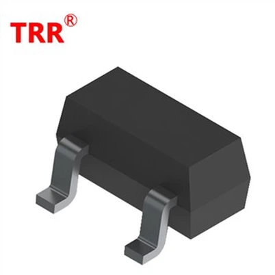
Small-signal diodes such as the BAV70 Diode, BAW56 Diode, and BAV99 Diode are widely used in medical devices for switching, protection, and signal routing. They are compact, fast, and cost-effective - but their small size also means limited thermal mass.
Many engineers or technicians initially assume "the diode is bad - just replace it." However, abnormal heating is often a symptom of deeper issues: insufficient design margin, mismatched operating conditions, poor PCB thermal design, or environmental factors. Simply swapping the part may provide temporary relief but risks recurrence, potential field failures, or compromised patient safety in medical applications.
Some Warmth Is Normal - Here's Where the Line Actually Is
All diodes generate heat during forward conduction due to the forward voltage drop (Vf, typically 0.7–1.0V for these parts). A slight temperature rise is expected. The critical metric is junction temperature (Tj), not surface temperature you can feel by hand.
Most datasheets for the BAV70, BAW56, and BAV99 specify a maximum Tj of 150°C. Exceeding this risks accelerated degradation, parameter drift, or catastrophic failure.
Use this approximation: Tj ≈ Ta + (P × RθJA) Where:
Ta = ambient temperature (°C)
P = power dissipation (Vf × If, in watts)
RθJA = junction-to-ambient thermal resistance (from datasheet, often 350–550 °C/W depending on PCB layout and manufacturer)
If calculated Tj approaches or exceeds 150°C, you have a problem.
Common Cause #1 - Exceeding Rated Forward Current
The most frequent culprit is operating beyond the rated continuous forward current (If). Datasheets list If max around 200–350 mA for these diodes (single diode loaded; check dual configurations carefully).
Power dissipation scales roughly with current: P ≈ Vf × If. Even modest overcurrents cause disproportionate heating. In medical devices, actual load conditions (e.g., during peaks, startup, or fault modes) may exceed design assumptions.
Diagnosis: Measure actual average and peak forward current in the circuit under worst-case conditions (temperature, voltage, load).
Common Cause #2 - Inadequate Derating for Ambient Temperature
Datasheet ratings are typically at Ta = 25°C. Medical devices often operate in higher ambient temperatures or enclosed spaces with poor ventilation. You must apply thermal derating - reducing allowable current/power as temperature rises.
Failure to derate during design is a common root cause of field overheating complaints.
Comparison Table - Common Diode Overheating Causes and How to Diagnose Each
|
Cause |
Typical Symptoms |
Diagnosis Method |
Recommended Fix |
|
Exceeding Forward Current |
Uniform heating, scales with load |
Current probe/measurement under load |
Reduce current or select higher-rated diode |
|
Insufficient Thermal Derating |
Worse at high ambient temps |
Calculate derated limits per datasheet |
Apply proper derating curves |
|
Poor PCB Thermal Design |
Hotspot localized to diode pads |
Thermal imaging + layout review |
Increase copper pours, add vias, heatsinking |
|
Component Defect/Batch Issue |
Random or one-sided in dual pkg |
Compare multiple units + datasheet specs |
Verify supplier quality; change lot |
|
Circuit Asymmetry (e.g., BAW56) |
One diode in package much hotter |
Measure both sections independently |
Balance loads or use separate diodes |
BAV70 Diode Checking If Your Design Left Enough Thermal Margin
For the BAV70 Diode (common cathode dual switching diode), review:
Max If: ~200–350 mA (varies by manufacturer)
Pd: ~225–350 mW
RθJA: ~350–556 °C/W
Tj max: 150°C
Measure actual If and calculate expected Tj. If margin is slim (<20–30°C below limit), redesign is advisable for medical reliability.
BAW56 Diode When One Side of a Dual Package Runs Hotter Than the Other
The BAW56 Diode (common anode) is popular for space-constrained designs. Asymmetric heating between the two internal diodes often indicates unequal loading in the two circuits rather than a defective part. Internal thermal coupling can also transfer heat.
Troubleshooting: Isolate and measure current through each diode section. Balance the design if possible.
BAV99 Diode Datasheet - Using Thermal Resistance Data to Calculate Expected Temperature Rise
The BAV99 Diode (series configuration) datasheet provides essential thermal data. Use the RθJA value to estimate temperature rise:
Example Calculation (simplified): At Ta = 50°C, If = 100 mA, Vf ≈ 0.8V → P ≈ 0.08W. With RθJA = 500 °C/W → Rise ≈ 40°C → Tj ≈ 90°C (acceptable).
Adjust for your exact conditions and PCB. Always consult the full BAV99 Diode Datasheet from your supplier for precise curves and notes.
PCB Layout and Thermal Path - The Overlooked Culprit
Even a perfectly spec-compliant diode will overheat with inadequate copper area, thin traces, or crowded layout. Thermal vias, larger pads, and copper pours are critical for heat spreading in dense medical boards.
Real Example - Diagnosing Diode Overheating
In one case with a medical client, production-line feedback highlighted BAV70 overheating. Investigation revealed actual circuit current exceeded design estimates by ~30% under peak load. Recalculation showed insufficient margin. The fix involved minor circuit adjustments and layout improvements - no diode replacement needed. Systematic analysis prevented broader recalls.
Common Mistakes When Diagnosing Diode Overheating
Replacing the diode without root-cause analysis.
Judging by touch alone instead of calculating Tj.
Ignoring ambient temperature derating.
Overlooking PCB thermal paths.
A Practical Checklist for Diagnosing Diode Overheating
Measure actual forward current and voltage under operating conditions.
Calculate power dissipation and expected Tj using datasheet RθJA.
Compare against derated limits for your ambient temperature.
Perform thermal imaging and review PCB layout.
Check for batch variability or supplier quality.
If Tj exceeds limits, redesign for better margin (higher-rated part, improved layout, or reduced stress).
FAQ
Q: Is it normal for a diode to feel warm during operation?
A: Yes, moderate warmth is expected. Abnormal is when Tj approaches datasheet maximum.
Q: What causes a diode to overheat in a circuit?
A: Excess current, poor derating, bad layout, or defects.
Q: How do I calculate a diode's expected temperature rise?
A: Tj ≈ Ta + (P × RθJA). Refer to the specific datasheet.
Q: What is thermal derating and why does it matter?
A: Reducing allowable power/current at higher temperatures to stay within Tj limits. Critical for medical reliability.
Final Thoughts - Heat Is a Symptom, Not Always the Root Cause
Abnormal diode heating in medical devices signals potential design or application gaps. A proactive, calculation-driven approach using datasheets for parts like the BAV70 Diode, BAW56 Diode, and BAV99 Diode ensures long-term reliability.
Work with experienced OEM diode suppliers who understand medical requirements and provide full technical support.
If you're facing diode overheating issues in your medical device project, share your circuit details or measurement data - our team can help review.
References and further reading: Manufacturer datasheets for BAV70/BAW56/BAV99