How Do You Use Thermal Imaging to Detect Diode Anomalies in Medical Devices?
Leave a message
Why Thermal Imaging Catches What Static Electrical Testing Can't
A multimeter or curve tracer measures a component's electrical behavior, forward voltage, reverse leakage, at the moment of testing, usually with the device powered down or running a controlled test signal. Thermal imaging measures something different: the actual temperature distribution across a board while it's operating under real, live load conditions.
These two approaches are complementary rather than competing. Many parametric failures, reverse leakage drift being a common example, tend to produce excess power dissipation, which shows up as heat. A component running measurably hotter than its neighbors under identical load conditions is a strong visual clue that something electrical is off, even before a single electrical measurement gets taken. Thermal imaging works well as a fast screening tool to flag which component deserves closer electrical testing, rather than as a replacement for that testing itself.
How Infrared Thermography Actually Works
Every object above absolute zero gives off infrared radiation, and the hotter it is, the more it emits. A thermal camera's detector picks up this infrared radiation and converts it into a visual temperature map, without needing to physically touch the component being inspected. This non-contact aspect matters a lot for a live circuit board, since you're reading temperature without risking a short from a test probe touching the wrong pad.
What a Normal vs Abnormal Thermal Signature Looks Like
A healthy diode operating under its intended load typically shows a modest, predictable temperature rise above the surrounding board temperature, and that rise should look broadly consistent across identical components performing the same function elsewhere on the same board. An abnormal signature generally shows up as one of a few patterns: a distinct, localized hot spot concentrated on a single component while neighbors stay cooler, an uneven temperature gradient across what should be a symmetric circuit layout, or a component that runs measurably hotter than its known-good counterparts under the same load.
It's worth being honest about the limits here: there's no single universal temperature threshold that applies across every circuit design, since acceptable operating temperature depends heavily on the specific component, its power dissipation under that particular load, and the surrounding thermal environment. The more reliable approach is comparative, checking a suspect component against other genuinely known-good units of the same type operating under the same conditions, rather than chasing an absolute number that doesn't really exist as a universal standard.
Here's how this plays out in practice. Suppose a board has six identical small-signal diodes performing the same function, and five of them show a temperature rise of roughly 8-12°C above ambient board temperature under normal operating load, a tight, consistent cluster. If the sixth shows a rise of 25°C or more under that same load, the absolute number matters less than the fact that it stands out clearly from its five otherwise-identical neighbors. That kind of outlier, identified purely through relative comparison rather than a fixed pass/fail threshold, is exactly the kind of finding worth escalating to electrical testing, regardless of whether 25°C would sound alarming or unremarkable in isolation without that comparison.
BAV70 Diode, Using Thermal Comparison Against Known-Good Baselines
When inspecting a BAV70 Diode on a populated board, the most reliable thermal comparison isn't against some generic published temperature figure, it's against other BAV70 components performing the identical function elsewhere on the same board, or against a known-good reference board running the same load. If every other instance of that same part sits within a tight, consistent temperature range and one specific unit runs noticeably hotter under matched conditions, that's a meaningful signal worth following up with electrical testing, regardless of what the absolute temperature number happens to be.
BAW56 Diode, Why Package Layout Matters for Thermal Interpretation
The BAW56 Diode package presents a specific interpretation challenge for thermal imaging. Since it's a dual-diode package with two separate diode elements sharing one physical body, heat generated by one internal diode can conduct through the shared package material and show up, at least partially, in a thermal reading taken over the other diode's location. This thermal crosstalk can make a healthy diode appear slightly warmer than expected simply because its neighbor inside the same package is running hot, not because it has a problem of its own.
This is exactly why a thermal hot spot on a dual-diode package like this should be treated as a prompt for individual electrical testing of each internal diode, rather than an automatic conclusion that both halves are equally affected. The thermal image tells you something's warm in that general location. It doesn't definitively tell you which specific internal diode is the actual source without follow-up testing.
BAV99 Diode Datasheet, Correlating Thermal Data With Reverse Leakage Specs
Elevated reverse leakage current in a diode generally increases power dissipation, and increased power dissipation generally shows up as extra heat. This connection is exactly why a thermal hot spot found on a BAV99 Diode is worth following up by checking actual reverse leakage measurements against the limits published in the BAV99 Diode Datasheet for that specific part, rather than treating the thermal finding alone as a confirmed failure.
This combined approach, thermal screening to flag a suspect component, followed by targeted electrical testing to confirm what's actually wrong, tends to be far more reliable than relying on either method in isolation. Thermal imaging is fast and can scan an entire board at once. Electrical testing is precise but requires knowing where to look first.
Comparison Table, Thermal Imaging vs Multimeter vs Curve Tracer
|
Method |
What It Detects |
Requires Power Down? |
Best Suited For |
|
Thermal imaging |
Abnormal heat distribution under real load conditions |
No, works on a live, operating circuit |
Fast screening across a whole board to identify suspect components |
|
Multimeter diode test |
Forward voltage, gross shorts/opens |
Usually yes, for a clean out-of-circuit reading |
Confirming a specific suspect component's basic condition |
|
Curve tracer |
Full I-V characteristic, subtle parametric drift, reverse leakage |
Yes, component typically tested in isolation |
Precise confirmation and detailed failure analysis of a flagged component |
Camera Resolution and Why Small SMD Packages Need Extra Care
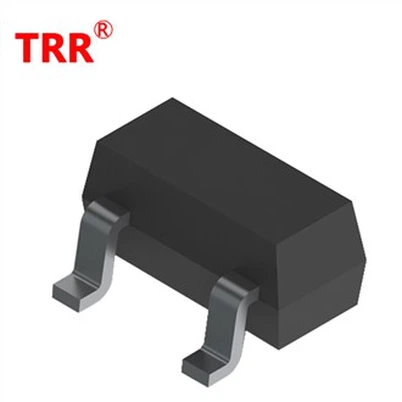
Small-signal diodes like the ones covered in this article commonly ship in tiny surface-mount packages, often SOT-23 or similarly compact formats, sometimes just a few millimeters across. This physical size creates a real practical challenge for thermal imaging: a camera with insufficient spatial resolution, or one positioned too far from the board, may not have enough pixels covering that tiny package to give a reliable, isolated temperature reading, instead blending it with the temperature of surrounding board area or neighboring components.
For dense, tightly populated boards using these small packages, getting close enough with an appropriately high-resolution thermal lens, sometimes called a macro or close-up lens attachment on dedicated thermal cameras, makes a meaningful difference in whether a genuine hot spot on a single small component gets identified clearly or gets averaged out and missed entirely within a broader, lower-resolution view of the board. Skipping this consideration is a realistic way for a real problem to go completely unnoticed on a thermal scan, not because the component wasn't actually running hot, but because the camera simply couldn't resolve it clearly enough at that distance and resolution.
Common Mistakes When Using Thermal Imaging for Component Diagnosis
Ignoring ambient temperature and airflow effects on readings. A component near a cooling fan or an open enclosure panel can read cooler than it would in normal sealed operation, and vice versa, skewing comparisons if conditions aren't consistent.
Relying on a single static image rather than observing behavior under varying load. Some issues only appear once the circuit has been running long enough to reach a steady thermal state, or under a specific operating mode.
Mistaking thermal crosstalk from a neighboring component for a fault in the component being inspected. As covered above with the BAW56 package, heat can conduct or radiate from a nearby source and distort the apparent location of the actual problem.
Using an incorrect emissivity setting on the thermal camera. Emissivity, a material property affecting how accurately a surface's true temperature is measured by infrared, needs to be set appropriately for the surface being measured (such as a component's plastic package versus bare solder), since an incorrect setting can produce a meaningfully inaccurate temperature reading even though the image itself looks perfectly normal.
A Step-by-Step Thermal Inspection Checklist
Set the correct emissivity value for the specific surface being measured before taking any reading, since this directly affects reading accuracy.
Let the device run under its actual intended operating load long enough to reach a stable thermal state before capturing images, rather than checking immediately after power-on.
Compare the suspect component against other known-good units of the same part performing the same function, rather than judging against an absolute temperature figure.
For dual-diode or multi-element packages, treat a hot spot as a prompt for individual testing of each internal element rather than an immediate conclusion.
Once a suspect component is identified thermally, move to targeted out-of-circuit electrical testing to confirm the actual nature of the problem before replacement.
Record ambient temperature, airflow conditions, and load state alongside thermal images, so results can be reproduced or compared later under matching conditions.
Industry Trends & Standards Relevant to Thermal Inspection
Infrared thermography practices in electronics inspection commonly reference ASTM E1934, a widely used standard practice covering examination procedures for infrared thermographic inspection of electrical and mechanical equipment, which provides general guidance on inspection conditions and reporting practices applicable to electronic assemblies.
Thermal imaging has also become more accessible to smaller repair and quality teams in recent years, as handheld and smartphone-attachable thermal camera options have dropped considerably in cost compared to the specialized, high-end equipment that was once required for this kind of inspection. This broader accessibility has made thermal screening a more routine part of quality control and field diagnostics in electronics servicing generally, rather than a technique reserved only for dedicated failure analysis labs. That said, the resolution limitation covered above for small SMD packages still applies regardless of price point, a budget camera aimed at a densely populated board from too far away will miss the same small hot spots a high-end unit would catch clearly at closer range, so equipment choice and technique still matter more than simply owning a thermal camera at all.
FAQ
Q: Can Thermal Imaging Detect A Failing Diode Before It Completely Fails?
A: Often, yes. Many failure modes, particularly those involving increased power dissipation like elevated reverse leakage, produce excess heat before a component fails completely, making thermal imaging a useful early screening tool ahead of a full functional failure that might otherwise only surface as an intermittent field issue.
Q: What Temperature Difference Indicates A Diode Problem?
A: There's no single universal threshold, since acceptable temperatures vary by component and circuit design. A more reliable approach is comparing the suspect component against other known-good units of the same type operating under matched load conditions, and treating a clear outlier relative to that baseline as the actual signal worth investigating.
Q: Does Thermal Imaging Replace Multimeter Or Curve Tracer Testing?
A: No. Thermal imaging is best used as a screening tool to identify which component deserves closer attention, while electrical testing methods confirm the actual nature and severity of a suspected problem.
Q: Why Do Two Diodes In The Same BAW56 Package Show Different Temperatures?
A: Since the package contains two independent diode elements, one can fail or run hot while the other remains healthy, and heat can also conduct between the two through the shared package material, making individual electrical testing necessary to identify the actual source.
Q: Does Emissivity Setting Affect Thermal Camera Accuracy?
A: Yes, significantly. Emissivity affects how accurately a thermal camera reads a surface's true temperature, and an incorrect setting for the material being measured can produce a noticeably inaccurate reading even though the captured image appears normal.
Q: Can Ambient Airflow Affect Thermal Imaging Results?
A: Yes. Airflow from cooling fans, open panels, or nearby ventilation can cool a component more than it would experience in normal sealed operation, so consistent conditions matter when comparing readings.
Q: What's The Difference Between Thermal Screening And Electrical Failure Confirmation?
A: Thermal screening quickly identifies which components show unusual heat patterns worth investigating, while electrical failure confirmation, using a multimeter or curve tracer, determines the actual specific nature and severity of the problem in that flagged component.
Q: Is Thermal Imaging Useful For Production Testing Or Just Field Repair?
A: Both. It's used in production quality control to catch assembly or component issues before shipment, and in field repair to diagnose intermittent or load-dependent problems that static electrical testing alone might miss.