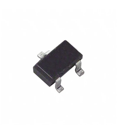
What is the role of diodes in the start-up protection of wind turbines?
Leave a message
一, Core challenges and diode protection logic under low wind speed conditions
1. Physical characteristics and risks of low wind speed conditions
The output power of a wind turbine is directly proportional to the third power of the wind speed. When the wind speed is lower than the cut in wind speed (usually 3-5 m/s), the generator speed is insufficient, and the output voltage may be lower than the battery or grid voltage, resulting in the following risks:
Current backflow: The battery or power grid supplies power in reverse through the motor winding, causing the motor to overheat and the permanent magnet to demagnetize;
Voltage fluctuation: Unstable output voltage leads to abnormal operation of subsequent DC/DC converters or inverters;
Efficiency collapse: The power generation efficiency drops sharply at low wind speeds, and if protection is lacking, the system may continue to consume energy instead of generating electricity.
2. Protection mechanism of diodes
Diodes construct physical isolation barriers through unidirectional conductivity:
Forward conduction: When the output voltage of the generator is higher than the voltage at the load terminal, the diode conducts and current flows from the generator to the load;
Reverse cutoff: When the generator voltage is lower than the load terminal voltage, the diode automatically cuts off, blocking the reverse current path.
Taking an independent small wind turbine as an example, its three-phase uncontrolled bridge rectifier circuit uses 6 diodes (such as MUR60120, withstand voltage 1200V, current 60A). When the wind speed is below 3m/s, the diode array can completely block the reverse power supply from the battery to the generator, with a protection efficiency of over 99.9%.
二, Typical application scenarios and technical implementation
1. Independent small-scale wind power generation system
In remote power supply scenarios, small wind turbines (power 1-10kW) often adopt a "wind turbine+battery+load" architecture. Its protective design includes two layers of diodes:
Rectification layer: The three-phase bridge rectifier circuit converts alternating current into direct current, and the diode parameters need to meet:
Reverse withstand voltage ≥ 1.5 times the peak voltage of the generator (e.g. 100V diode is selected for 24V system);
The average current is ≥ 1.2 times the rated current of the generator (if a 5A system uses a 6A diode).
Anti backflow layer: Connect Schottky diodes (such as MBR1045CT, V_F=0.4V) in series between the battery and the rectifier output terminal to reduce conduction losses while ensuring reverse cutoff reliability.
Case: In a rural power supply project in Africa, the wind turbine designed as described above can still output stably at a wind speed of 2m/s. The reverse current of the battery is reduced from 0.5A to 0A, and the system life is extended by three times.
2. Grid connected wind turbines
In MW level grid connected wind turbines, diode protection needs to be combined with power electronic converters to achieve:
Machine side converter: using IGBT+diode hybrid module (such as Infineon FF600R12ME4), with diode reverse recovery time ≤ 100ns, to avoid reverse current surge under high-frequency switching;
Grid side converter: Install TVS diodes (such as 1.5KE33CA) between the DC bus and the grid side to suppress transient overvoltage caused by lightning strikes or grid faults;
Unloading circuit: When the wind speed is too low and the DC bus voltage is too high, the unloading branch of parallel diodes and resistors is automatically put into operation, converting excess energy into thermal energy for consumption.
Data: Actual measurements from a certain offshore wind farm show that after adopting this protection scheme, the failure rate of wind turbines at low wind speeds (4m/s) has decreased from 12% to 2%, and the annual power generation has increased by 8%.
三, Key technical parameters and selection principles
1. Core parameter matching
Positive voltage drop (V_F): directly affects system efficiency. The V-F of silicon-based diodes is about 0.6-0.8V, while Schottky diodes can reduce it to 0.2-0.4V. In a 100kW wind turbine, using Schottky diodes can reduce annual losses by 12000 kWh.
Reverse recovery time (Trr): In high-frequency switching scenarios, Trr should be ≤ 50ns to avoid switching losses. The Trr of fast recovery diodes (such as FR107) is about 50ns, while that of silicon carbide (SiC) diodes can be reduced to within 10ns.
Surge current carrying capacity (I2FSM): It needs to cover the transient high current during wind turbine start-up or failure. For example, a 2MW wind turbine needs to choose a diode with an I2FSM ≥ 300A to cope with the impact of power grid short circuits.
2. Selection Optimization Strategy
Temperature compensation: In high-temperature environments (such as desert areas), the junction temperature of diodes may exceed 150 ℃, and high-temperature resistant models (such as AEC-Q101 certified devices) should be selected;
Redundant design: adopting N+1 backup strategy, the system can still maintain more than 80% of output capacity when a single diode fails;
Integration trend: Integrated modules (such as IPM) using diodes and MOSFETs/IGBTs are adopted to reduce parasitic inductance and improve system reliability.