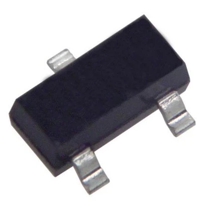
How to use a multimeter to test diodes in an energy system?
Leave a message
一, The core principle of diode testing: understanding the PN junction characteristics
The essence of a diode is a PN junction, and its core characteristics include:
Unidirectional conductivity: forward conduction (low resistance), reverse cutoff (high resistance).
Forward voltage drop (Vf): The typical value for silicon diodes is 0.6-0.7V, and for Schottky diodes it is 0.2-0.4V.
Reverse breakdown voltage (Vbr): After exceeding the threshold, the diode is permanently damaged.
The core logic of a multimeter to test a diode is to apply a small current (forward) or voltage (reverse), measure its resistance or voltage drop, and determine whether the PN junction is intact.
二, Preparation before testing: tool selection and environmental requirements
1. Selection of multimeter
Digital Multimeter (DMM): It is recommended to use models that support the diode test mode, such as Fluke 87V, UT61E, etc. The test voltage is usually 2.8V (forward) and -3V (reverse), with a current of about 1mA, which will not damage the diode.
Analog multimeter: It is necessary to manually select the resistance range (such as the x 1k Ω range), but it should be noted that the test voltage may exceed the diode threshold, which poses a risk of misjudgment.
2. Testing environment requirements
Temperature control: The diode parameters vary significantly with temperature (such as Vf decreasing by about 2mV for every 10 ℃ increase), and it is recommended to test in an environment of 25 ℃.
Power off operation: The power supply of the energy system must be disconnected to avoid the risk of high-voltage electric shock or short circuit.
Anti static measures: Use an anti-static wristband to prevent static electricity from penetrating sensitive diodes (such as MOSFET built-in diodes).
3, Step by Step Testing Guide: From Basic to Advanced
Step 1: Preliminary Appearance Inspection
Visual inspection: Observe whether the diode pins are oxidized, whether the packaging is cracked, and whether the solder joints are loose.
Tag recognition: Confirm the diode model (such as 1N4007, MBR2045CT) and polarity (anode "+", cathode "-").
Step 2: Multimeter settings
Digital multimeter: Turn the knob to "diode test mode" (the icon is a triangle with an arrow).
Analog multimeter: Select the "× 1k Ω" resistance range, connect the red probe to the positive terminal and the black probe to the negative terminal.
Step 3: Positive conductivity test
Connect the probes: Connect the red probe to the anode of the diode and the black probe to the cathode.
Read values:
Digital multimeter: displays forward voltage drop (Vf), silicon diode should be 0.5-0.7V, Schottky diode should be 0.2-0.4V.
Analog multimeter: If the pointer deviates to a low resistance value (such as a few hundred ohms), there may be an open circuit if the pointer does not move.
Judgment criteria:
Normal: Vf is within the specification range and displays "OL" (overload) during reverse testing.
Exception: Vf=0V (short circuit) or Vf>1V (open circuit or performance degradation).
Step 4: Reverse Cut off Test
Reverse probe: Connect the red probe to the cathode and the black probe to the anode.
Read values:
Digital multimeter: displays "OL" or high resistance value (usually>1M Ω).
Analog multimeter: The pointer hardly moves (high resistance).
Judgment criteria:
Normal: The reverse resistance is extremely high and there is no significant leakage current.
Exception: Reverse voltage drop<0.3V or resistance<100k Ω (large leakage current, possible breakdown).
Step 5: Dynamic parameter testing (optional)
For critical applications such as high-power diodes, further testing is required:
Forward recovery time (trr): Use an oscilloscope to observe the transition time of the diode from reverse cutoff to forward conduction, trr should be less than 100ns (fast recovery diode).
Reverse recovery charge (Qrr): Calculated by integrating the reverse current curve, the smaller the Qrr, the lower the switching loss.
4, Typical application scenarios and fault diagnosis in energy systems
Scenario 1: PV module bypass diode test
Problem manifestation: Component hot spots and decreased output power.
Test steps:
Disconnect the component from the combiner box.
Test the forward voltage drop of the bypass diode. If Vf>0.7V (silicon tube) or>0.45V (Schottky tube), it needs to be replaced.
Reverse testing should display "OL". If the leakage current is greater than 10 μ A, it may cause thermal runaway.
Case: In a 5MW photovoltaic power station, 12% of the bypass diodes suffered a component efficiency loss of over 5% due to an increase in Vf, which was restored after replacement.
Scenario 2: Testing of MOSFET built-in diodes in energy storage systems
Problem manifestations: Abnormal battery charging and discharging, BMS reporting malfunction.
Test steps:
Disassemble the MOSFET module and test the forward voltage drop of the body diode.
Compared to components from the same batch, if the Vf deviation is greater than 10%, there may be a process defect.
Case: In a certain energy storage cabinet, uneven parallel current caused by inconsistent MOSFET diode Vf resulted in local overheating.
Scenario 3: Testing of rectifier diodes in electric vehicle charging modules
Problem manifestations: Decreased charging efficiency and diode burnout.
Test steps:
Use a thermal imaging device to locate the high-temperature diode.
Test the Vf and reverse resistance of the high-temperature diode. If Vf>0.8V or reverse resistance<500k Ω, replace it immediately.
Case: A charging station suffered from module burnout due to large reverse leakage current of rectifier diode, resulting in maintenance costs exceeding 20000 yuan.
5, Common Problems and Solutions
Problem 1: Unstable test values
Reason: Poor contact of the probe and thermal effect of the diode.
Solution: Clean the probes and pins to quickly complete the test (avoid prolonged power on heating).
Problem 2: Analog multimeter misjudgment
Reason: The test voltage in the x 1k Ω range may exceed the diode threshold.
Solution: Use a digital multimeter or connect a 1k Ω resistor in series for current limiting.
Question 3: Dispersion of diode parameters
Reason: There is a deviation of ± 5% in Vf between different batches of components.
Solution: Establish a parameter benchmark library and compare the test results of components from the same batch.
6, Advanced technique: Combining other tools to improve diagnostic efficiency
Thermal imaging assistance: Quickly locate faulty diodes through temperature distribution (abnormal diode temperature is 10-20 ℃ higher than normal).
LCR tester: measures the diode junction capacitance (Cj). If Cj significantly deviates from the specification value (such as increasing from 100pF to 500pF), there may be a risk of breakdown.
Curve tracker: Draw I-V characteristic curves to accurately determine diode soft breakdown or parameter drift.
7, Safety regulations and operating taboos
Prohibited live testing: The high voltage of the energy system can reach 1000V or above, and live operation may cause arcing or electric shock.
Avoid reverse high voltage: The reverse voltage of the multimeter diode test range is only 3V, but if the high voltage range (such as 20V) is mistakenly used, the diode may break down.
Anti static requirements: When handling sensitive diodes (such as SiC MOSFET built-in diodes), they must be operated on an anti-static workbench.