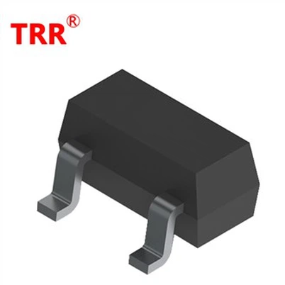
How to prevent lightning strikes and surges in TVS diodes in medical equipment?
Leave a message
一, The threat of lightning strikes and surges to medical equipment
Lightning strikes threaten medical equipment in two ways:
Direct lightning strike: Lightning strikes buildings or equipment enclosures, causing a sudden increase in ground potential, creating a potential difference, and damaging equipment insulation;
Induced lightning strike: Lightning electromagnetic pulses invade equipment through power lines, signal lines, or spatial coupling, generating transient high voltage spikes and damaging sensitive electronic components.
Medical equipment is extremely sensitive to voltage fluctuations. For example, the X-ray tube of a CT scanner requires stable DC high voltage, while the signal acquisition circuit of an electrocardiograph relies on a low-noise DC power supply. Transient overvoltage may cause equipment failure, data loss, and even secondary disasters such as fires. According to statistics, 80% of medical equipment damage cases caused by lightning strikes worldwide each year are related to surge intrusion into power or signal lines.
二, The technical principle and core advantages of TVS diodes
TVS diode is a semiconductor device based on PN junction avalanche breakdown effect, and its core function is:
Transient response: When the voltage exceeds the breakdown voltage (VBR), the TVS transitions from a high resistance state to a low resistance state within 1 nanosecond, forming a conductive path;
Precise clamping: Under the action of peak pulse current (IPP), clamp the voltage at the maximum clamping voltage (Vc) to ensure that the voltage of the subsequent circuit is below the safety threshold;
Automatic recovery: After the surge disappears, the TVS automatically returns to a high impedance state without manual intervention and can be reused.
Compared to traditional protective devices such as MOV and GDT, TVS has the following advantages:
Extremely fast response speed: MOV requires thermal accumulation to conduct, GDT requires gas ionization time, and TVS response time reaches picosecond level;
Low clamping voltage: The dynamic resistance of TVS can be as low as 0.1 Ω, and the residual voltage (Vc) is significantly lower than that of MOV;
Compact size: Surface mount TVS (such as SMAJ series) has a volume of only 0.1 cubic centimeters, suitable for compact medical devices;
Long lifespan: It can withstand hundreds of surge impacts, while MOVs experience significant performance degradation after multiple impacts.
三, Typical applications of TVS diodes in medical equipment
1. Power module protection
The power module of medical equipment needs to convert the mains power (220V/50Hz) into a stable DC voltage. The TVS diode converts AC power into pulsating DC power through a bridge rectifier circuit and a filtering capacitor, and then outputs a smooth voltage after being clamped by the TVS. For example, the power module of a certain hemodialysis machine uses four 1N5408 silicon rectifier diodes to form a rectifier circuit, and is connected in parallel with SMAJ5.0CA TVS (Vc=6.5V) to protect the rear DC/DC converter. When lightning strikes cause the input voltage to suddenly increase to 300V, the TVS conducts within 10ns, clamping the voltage to 6.5V to avoid damage to the converter.
2. Signal line protection
The signal lines of medical equipment, such as the electrocardiogram signal acquisition line of an electrocardiograph and the probe signal line of an ultrasound diagnostic device, are sensitive to noise. TVS diodes are designed with low capacitance (such as LCESeries junction capacitance of only 0.5pF) to suppress surges while reducing signal distortion. For example, a 12 lead electrocardiogram machine uses BAS70-04 type limiting diode (Vc=7V) to protect the input end of the electrocardiogram signal. When the signal voltage exceeds ± 7V, TVS conducts, limiting the voltage within a safe range and ensuring that the signal-to-noise ratio (SNR) of the electrocardiogram waveform is ≥ 60dB.
3. Communication interface protection
The communication interfaces of medical equipment, such as RS-485 and CAN bus, must meet electromagnetic compatibility (EMC) requirements. TVS diodes protect differential signal lines through bidirectional configuration. For example, the RS-485 communication interface of a shadowless light in a certain operating room uses SR05-4 bidirectional TVS (Vc=10V). When the lightning induced voltage is transmitted along the twisted pair, the GDT (gas discharge tube) first conducts and amplifies the current, and the residual rapid rising edge is captured and clamped to below 10V by the TVS within 1ns to ensure uninterrupted communication.
四, Selection and design points of TVS diodes
1. Selection of key parameters
Reverse Cut off Voltage (VRMM): It should be slightly higher than the normal operating voltage of the protected circuit. For example, a 12V power supply circuit should choose a TVS with VRMM=14V;
Breakdown voltage (VBR): usually 1.1-1.2 times that of VRMM, ensuring no misoperation during normal voltage fluctuations;
Maximum clamping voltage (Vc): must be lower than the absolute maximum withstand voltage of the subsequent circuit. For example, the IO port withstand voltage of a 3.3V MCU is 5.5V, and the Vc of a TVS should be ≤ 4.5V;
Peak Pulse Current (IPP): It needs to be selected according to surge testing standards (such as IEC 61000-4-5 Level 4). For example, in the face of ± 4kV surge testing, a TVS with IPP ≥ 1500W needs to be selected;
Junction capacitance (Cj): Low capacitance TVS (such as SACSeries junction capacitance ≤ 0.3pF) should be selected for high-speed signal lines to avoid signal distortion.
2. Multi level protection design
Medical equipment usually adopts a three-level protection scheme of "GDT+TVS+filtering":
First level (GDT): responsible for over 90% of energy release, with high pressure resistance and large current flow, but slow response;
Level 2 (TVS): Fast response to residual spikes, precise clamping to IC acceptable range;
Third level (filtering): A π - type filter composed of magnetic beads and ceramic capacitors is used to suppress high-frequency noise.
Adequate creepage distance (≥ 2mm) should be maintained between different levels to avoid high-voltage breakdown of the PCB surface.
3. Layout and heat dissipation optimization
Arrange near the connector entrance: reduce parasitic inductance of the wiring. For every 1nH increase in inductance, additional voltage drop will be generated under high di/dt surges;
Large area copper connection protection ground (PGND): It is recommended to have a wiring width of ≥ 20mil to avoid surge currents passing through the digital ground plane;
Heat dissipation design: A heat dissipation via array should be added below high-power TVS (such as SMC, DO-201 packaging), and thermal conductive silicone grease should be used if necessary.